Theorie
Het is van essentieel belang om de theorie goed te begrijpen zodat je de praktische opdrachten in het labo succesvol kan uitvoeren !!!
*** IN OPBOUW ***
Inleiding
Virtual eXtensible LAN (VXLAN) is een netwerkvirtualisatietechnologie die de schaalbaarheidsproblemen in cloud- en datacenter-oplossingen wenst te verhelpen. Concreet hebben L2-netwerken volgende uitdagingen:
- Spanning tree (Inefficiënt gebruik van bandbreedte, trage convergentie, ...)
- Beperkt aantal VLAN's (12-bit VLAN ID)
- De grootte van MAC-adres tabellen. (Beperkte CAM-geheugencapaciteit, hogere belasting, ... )
VXLAN staat beschreven in RFC 7348. Hierbij maakt VXLAN gebruik van een overlay network of tunnel.
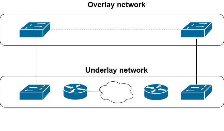
Overlay network vs underlay network
Een overlay network is een virtueel netwerk die zich bovenop het fysieke netwerk (underlay network) bevindt. Bij VXLAN situeert het overlay network zich op laag 2 en het underlay network op laag 3 van het OSI-model.
VXLAN Network Identifier (VNI)
Vergeleken met IEEE 802.1Q tag (12-bit) verhoogt VNI (24-bit) de schaalbaarheid tot meer dan 16 miljoen logische netwerken. De VNI identificeert een VXLAN en heeft een gelijkaardige functie als een VLAN ID.
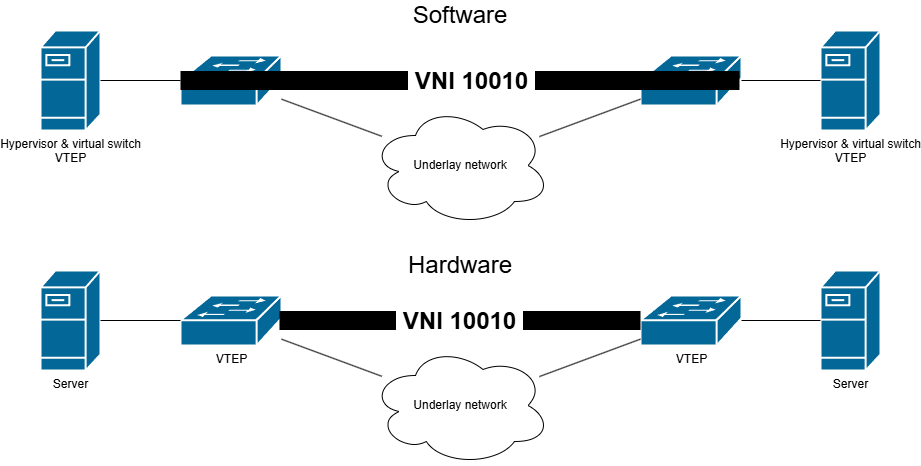
VXLAN Tunnel EndPoint (VTEP)
VXLAN endpoints beëindigen VXLAN-tunnels. Een VTEP is het verbindingspunt tussen het overlay en he underlay network. Een VTEP kan zowel voorkomen in software (bijvoorbeeld een hypervisor) als in hardware (bijvoorbeeld een router of een switch).
Interfaces
Iedere VTEP bevat uit 2 types van interfaces:
- VTEP IP interface (Underlay network)
- VNI interface (Overlay network)
VXLAN (Basic)
Framestructuur
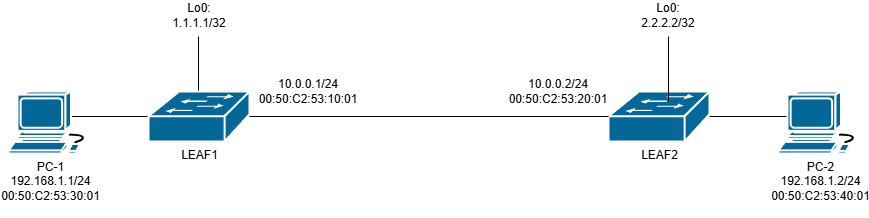
Aan de hand van een eenvoudig voorbeeld tonen we de werking. In onderstaande figuur vind je de gebruikte topologie.
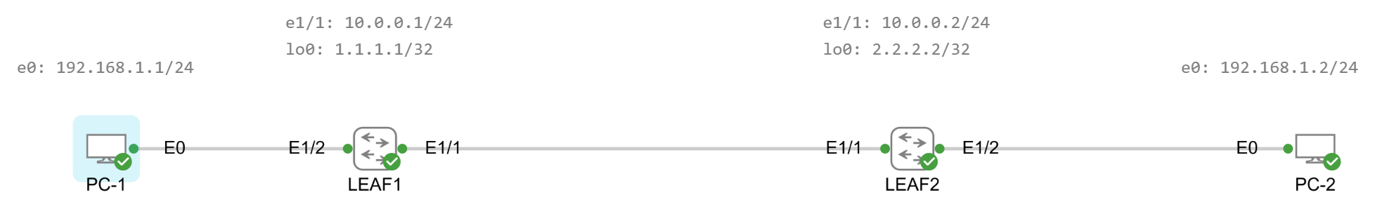
We pingen vanaf PC-1 (192.168.1.1/24) naar PC-2 (192.168.1.2/24). Gelijktijdig capteren we netwerkverkeer op 3 plaatsen.
- De verbinding tussen PC-1 en LEAF1
- De verbinding tussen LEAF1 en LEAF2
- De verbinding tussen LEAF2 en PC-2
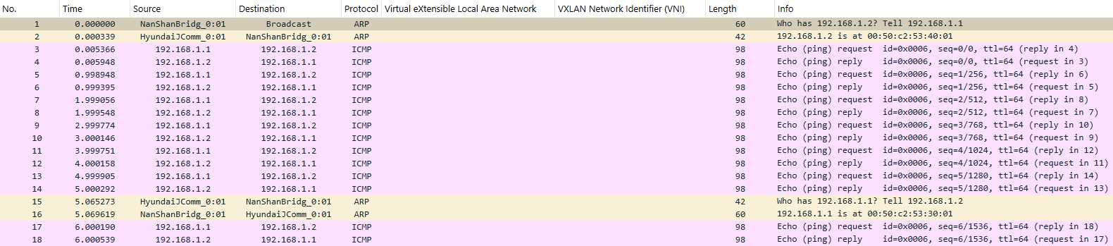
In onderstaande figuur vind je het netwerkverkeer tussen PC-1 en LEAF1.
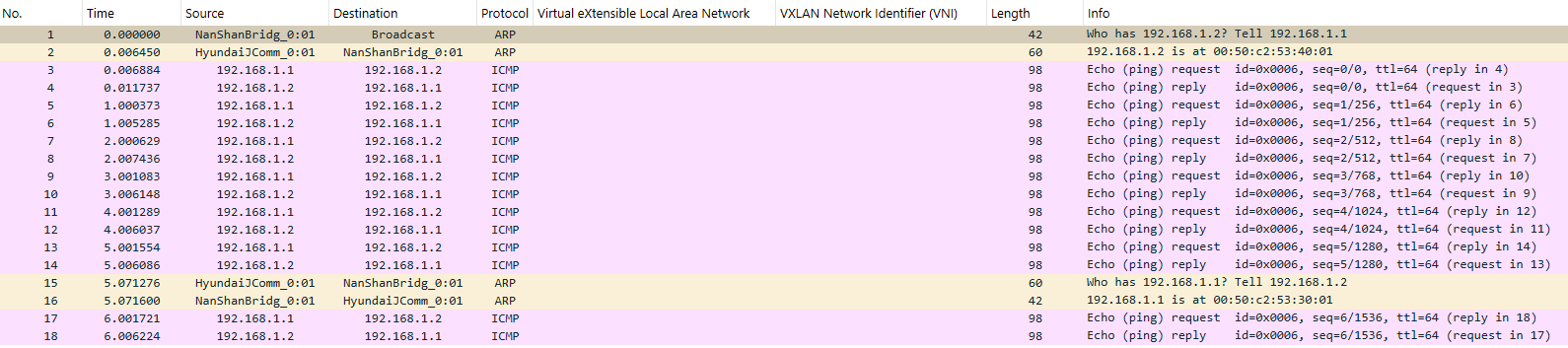
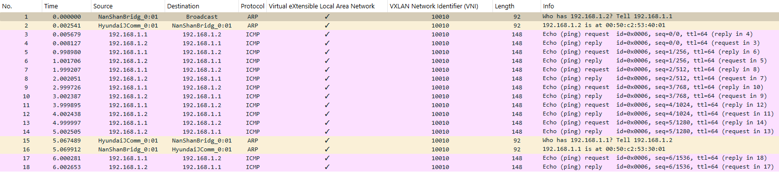
In onderstaande figuur vind je het netwerkverkeer tussen LEAF1 en LEAF2.
In onderstaande figuur je het netwerkverkeer tussen LEAF2 en PC-2.
Het gebruik wan VXLAN is duidelijk aanwezig tussen LEAF1 en LEAF2.
Hoeveel overhead (grootte van een frame) veroorzaakt VXLAN?
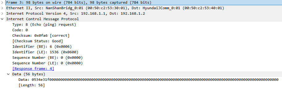
Laat ons iets dieper graven. De analyse van frame 3 vind je hieronder.
In onderstaande figuur vind je gedetailleerd overzicht van frame 3 tussen PC-1 en LEAF1.
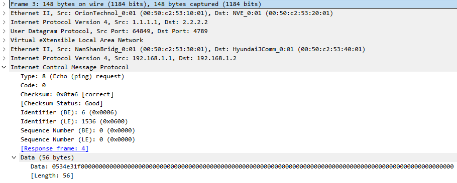
In onderstaande figuur vind je gedetailleerd overzicht van frame 3 tussen LEAF1 en LEAF2.
In onderstaande figuur vind je gedetailleerd overzicht van frame 3 tussen LEAF2 en PC-2.
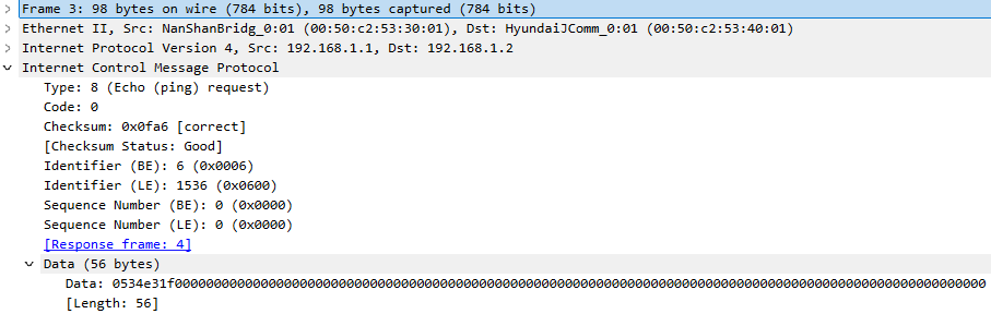
De bovenstaande figuur (LEAF1 - LEAF2) toont duidelijk de extra headers (IPv4, UDP, VXLAN) die VXLAN met zich meebrengt.
Een grafische voorstelling van deze header zie je in onderstaande figuur.
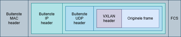
Het officiële UDP-poortnummer voor VXLAN is 4789.
Gedetailleerde studie
We hernemen de reeds besproken topologie. In onderstaande figuur vind je alle nodige informatie.
Beide computers (PC-1 en PC-2) zijn zich niet bewust van VXLAN. Beide switches (LEAF1 en LEAF2) beschikken over de VTEP functionaliteit.
- Stap 1: PC-1 verstuurt een Ethernet frame met als bestemming PC-2.
- Stap 2: LEAF1 ontvangt deze Ethernet frame op de VNI interface.
- Stap 3: LEAF1 achterhaalt aan welk VNI PC-1 is gekoppeld.
- Stap 4: LEAF1 bekomt het verband tussen het MAC-adres van PC-2 en het remote VTEP IP-adres.
- Stap 5: LEAF1 voegt de VXLAN header toe.
- Stap 6: LEAF1 voegt de buitenste UDP header toe.
- Stap 7: LEAF1 voegt de buitenste IP header toe.
- Stap 8: LEAF1 voegt de buitenste frame header toe.
- Stap 9: LEAF1 verstuurt deze frame over het underlay network.
- Stap 10: LEAF2 ontvangt deze frame en verwerkt de buitenste frame header.
- Stap 11: LEAF2 leest het pakket en verwerkt de buitenste IP header.
- Stap 12: LEAF2 controleert de VNI en zoekt naar de interface waarop het MAC-adres van PC-2 gekend is.
- Stap 13: PC-2 ontvangt het Ethernet frame.
Stap 4 is hierbij een vreemde stap. Hoe kan LEAF1 deze informatie bekomen?
Bij VXLAN zal iedere VTEP een VXLAN mapping table bijhouden. Deze tabel bevat de link tussen het MAC-adres van de destinatie en het remote VTEP IP-adres.
Deze tabel kan op vier verschillende manieren opgebouwd worden:
- VXLAN met static ingress replication
- VXLAN met multicast underlay
- VXLAN met MP-BGP EVPN
- VLAN met LISP
VXLAN met static ingress replication
Deze werkwijze is de meest eenvoudige en is enkel geschikt voor kleinere netwerken. De manuele configuratie zorgt namelijk voor een beperkte schaalbaarheid.
Onderstaande configuratie werd uitgevoerd op Cisco Nexus 9000v Switches.
In onderstaande figuur vind je nogmaals de reeds besproken topologie.
We splitsen de configuratie op in verschillende stappen:
Underlay network
Hieronder vind je een basisconfiguratie uitgebreid met een loopback interface (noodzakelijk voor VTEP) en OSPF als routing protocol.
hostname LEAF1
feature ospf
router ospf 1
interface Ethernet1/1
  no switchport
  mac-address 0050.c253.1001
  ip address 10.0.0.1/24
  ip ospf network point-to-point
  ip router ospf 1 area 0.0.0.0
  no shutdown
interface loopback0
  ip address 1.1.1.1/32
  ip router ospf 1 area 0.0.0.0
hostname LEAF2
feature ospf
router ospf 1
interface Ethernet1/1
  no switchport
  mac-address 0050.c253.2001
  ip address 10.0.0.2/24
  ip ospf network point-to-point
  ip router ospf 1 area 0.0.0.0
  no shutdown
interface loopback0
  ip address 2.2.2.2/32
  ip router ospf 1 area 0.0.0.0
Overlay network
Hieronder vind je de configuratie omtrent VXLAN Network Identifier (VNI). Deze configuratie bestaat uit 3 delen.
- Het activeren van een feature (vn-segment).
- Een VLAN koppelen aan een VNI.
- Een VLAN toekennen aan een interface.
Deze configuratie is aanwezig op beide switches (LEAF1 en LEAF2).
feature vn-segment-vlan-based
vlan 10
  vn-segment 10010
interface Ethernet1/2
  switchport access vlan 10
Hieronder vind je de configuratie omtrent Network Virtual Interface (NVE).
Configuratie LEAF1
feature nv overlay
interface nve1
  no shutdown
  source-interface loopback0
  member vni 10010
    ingress-replication protocol static
      peer-ip 2.2.2.2
Configuratie LEAF2
feature nv overlay
interface nve1
  no shutdown
  source-interface loopback0
  member vni 10010
    ingress-replication protocol static
      peer-ip 1.1.1.1
Controle underlay network
Hier volstaat een eenvoudige connectiviteitstest tussen de loopback interfaces.
LEAF1# ping 2.2.2.2 source 1.1.1.1
PING 2.2.2.2 (2.2.2.2) from 1.1.1.1: 56 data bytes
64 bytes from 2.2.2.2: icmp_seq=0 ttl=254 time=4.757 ms
64 bytes from 2.2.2.2: icmp_seq=1 ttl=254 time=4.219 ms
64 bytes from 2.2.2.2: icmp_seq=2 ttl=254 time=2.482 ms
64 bytes from 2.2.2.2: icmp_seq=3 ttl=254 time=2.247 ms
64 bytes from 2.2.2.2: icmp_seq=4 ttl=254 time=2.1 ms

--- 2.2.2.2 ping statistics ---
5 packets transmitted, 5 packets received, 0.00% packet loss
round-trip min/avg/max = 2.1/3.16/4.757 ms
LEAF1#
Controle overlay network
Een eerste controle is de mapping tussen VLAN en VNI.
LEAF1# show vxlan
Vlan            VN-Segment
====            ==========
10              10010
LEAF1#
Een tweede controle is de NVE interface.
LEAF1# show nve peers
Interface Peer-IP                                 State LearnType Uptime   Router-Mac
--------- --------------------------------------  ----- --------- -------- -----------------
nve1      2.2.2.2                                 Up    DP        2w0d     n/a

LEAF1#
LEAF1# show nve vni
Codes: CP - Control Plane        DP - Data Plane
       UC - Unconfigured         SA - Suppress ARP
       S-ND - Suppress ND
       SU - Suppress Unknown Unicast
       Xconn - Crossconnect
       MS-IR - Multisite Ingress Replication
       HYB - Hybrid IRB mode

Interface VNI      Multicast-group   State Mode Type [BD/VRF]      Flags
--------- -------- ----------------- ----- ---- ------------------ -----
nve1      10010    UnicastStatic     Up    DP   L2 [10]

LEAF1#
LEAF1# show nve interface
Interface: nve1, State: Up, encapsulation: VXLAN
 VPC Capability: VPC-VIP-Only [not-notified]
 Local Router MAC: 52ee.bd1b.1b08
 Host Learning Mode: Data-Plane
 Source-Interface: loopback0 (primary: 1.1.1.1, secondary: 0.0.0.0)

LEAF1#
Bestudeer uitgebreid het verkregen resultaat van bovenstaande commando's.
VXLAN met multicast underlay
Door gebruik te maken van multicast zal iedere VTEP gekoppeld worden aan een VNI a.d.h.v. een multicast groep.
Onderstaande configuratie werd uitgevoerd op Cisco Nexus 9000v Switches.
In onderstaande figuur vind je de gebruikte topologie.
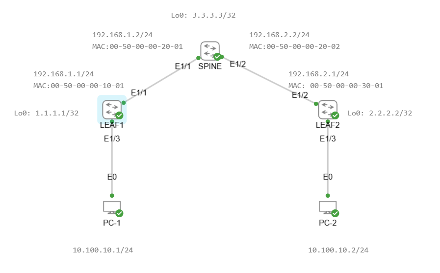
We pingen vanaf PC-1 (10.100.10.1/24) naar PC-2 (10.100.10.2/24). Gelijktijdig capteren we netwerkverkeer op 4 plaatsen.
- De verbinding tussen PC-1 en LEAF1
- De verbinding tussen LEAF1 en SPINE
- De verbinding tussen SPINE en LEAF2
- De verbinding tussen LEAF2 en PC-2
De resultaten zijn vergelijkbaar met voorgaande opstelling.
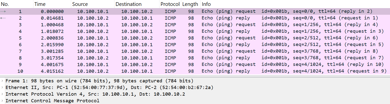
In onderstaande figuur vind je het netwerkverkeer tussen PC-1 en LEAF1.
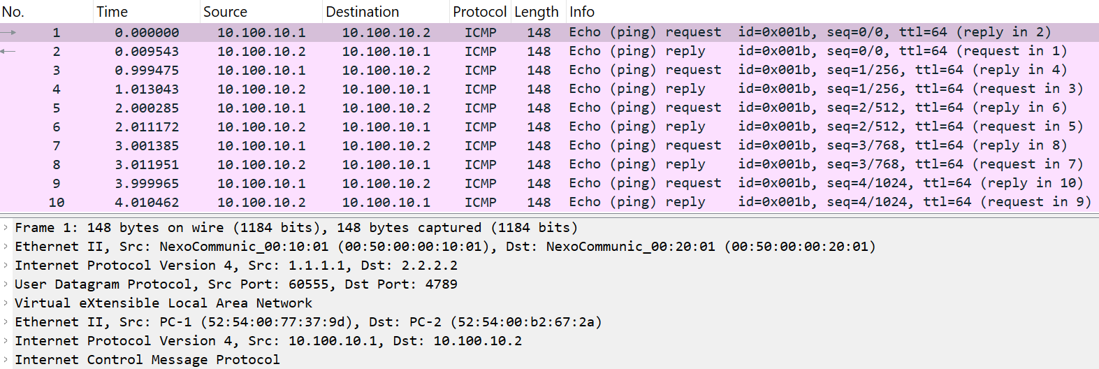
In onderstaande figuur vind je het netwerkverkeer tussen LEAF1 en SPINE.
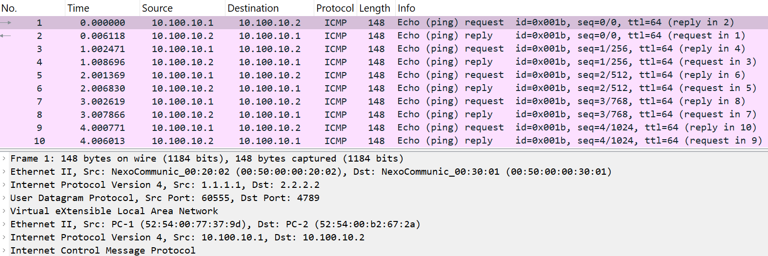
In onderstaande figuur vind je het netwerkverkeer tussen SPINE en LEAF2.
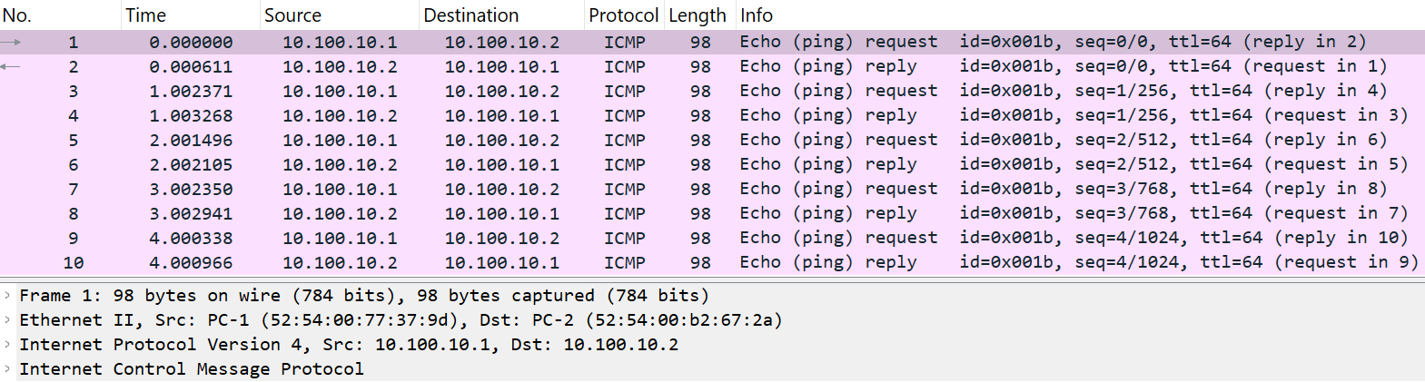
In onderstaande figuur je het netwerkverkeer tussen LEAF2 en PC-2.
De onderliggende configuratie is echter volledig verschillend.
We splitsen de configuratie terug op in verschillende stappen:
Underlay network
Hier configureren we de IP-adressen, routering en multicast.
Initieel vind je de configuratie van de IP-adressen en routering terug.
hostname LEAF1

feature ospf

interface Ethernet1/1
  no switchport
  mac-address 0050.0000.1001
  ip address 192.168.1.1/24
  ip ospf network point-to-point
  ip router ospf 1 area 0.0.0.0
  no shutdown

interface loopback0
  ip address 1.1.1.1/32
  ip router ospf 1 area 0.0.0.0

router ospf 1
hostname SPINE

feature ospf

interface Ethernet1/1
  no switchport
  mac-address 0050.0000.2001
  ip address 192.168.1.2/24
  ip ospf network point-to-point
  ip router ospf 1 area 0.0.0.0
  no shutdown

interface Ethernet1/2
  no switchport
  mac-address 0050.0000.2002
  ip address 192.168.2.2/24
  ip ospf network point-to-point
  ip router ospf 1 area 0.0.0.0
  no shutdown

interface loopback0
  ip address 3.3.3.3/32
  ip router ospf 1 area 0.0.0.0

router ospf 1
hostname LEAF2

feature ospf

interface Ethernet1/2
  no switchport
  mac-address 0050.0000.3001
  ip address 192.168.2.1/24
  ip ospf network point-to-point
  ip router ospf 1 area 0.0.0.0
  no shutdown

interface loopback0
  ip address 2.2.2.2/32
  ip router ospf 1 area 0.0.0.0

router ospf 1
Het configureren van multicast bestaat uit 3 onderdelen:
- Activeer multicast
- Plaats de interfaces in PIM sparse mode
- Configureer de loopback interface van SPINE1 als statische
Rendezvous Point (RP).
hostname LEAF1

feature pim

ip pim rp-address 3.3.3.3

interface Ethernet1/1
  no switchport
  mac-address 0050.0000.1001
  ip address 192.168.1.1/24
  ip ospf network point-to-point
  ip router ospf 1 area 0.0.0.0
  ip pim sparse-mode
  no shutdown

interface loopback0
  ip address 1.1.1.1/32
  ip router ospf 1 area 0.0.0.0
  ip pim sparse-mode
hostname SPINE

feature pim

ip pim rp-address 3.3.3.3

interface Ethernet1/1
  no switchport
  mac-address 0050.0000.2001
  ip address 192.168.1.2/24
  ip ospf network point-to-point
  ip router ospf 1 area 0.0.0.0
  ip pim sparse-mode
  no shutdown

interface Ethernet1/2
  no switchport
  mac-address 0050.0000.2002
  ip address 192.168.2.2/24
  ip ospf network point-to-point
  ip router ospf 1 area 0.0.0.0
  ip pim sparse-mode
  no shutdown

interface loopback0
  ip address 3.3.3.3/32
  ip router ospf 1 area 0.0.0.0
  ip pim sparse-mode
hostname LEAF2

feature pim

ip pim rp-address 3.3.3.3

interface Ethernet1/2
  no switchport
  mac-address 0050.0000.3001
  ip address 192.168.2.1/24
  ip ospf network point-to-point
  ip router ospf 1 area 0.0.0.0
  ip pim sparse-mode
  no shutdown

interface loopback0
  ip address 2.2.2.2/32
  ip router ospf 1 area 0.0.0.0
  ip pim sparse-mode
Overlay network
Hieronder vind je de configuratie omtrent VNI terug.
hostname LEAF1

feature vn-segment-vlan-based

vlan 10
  vn-segment 10010

interface Ethernet1/3
  switchport access vlan 10
hostname LEAF2

feature vn-segment-vlan-based

vlan 10
  vn-segment 10010

interface Ethernet1/3
  switchport access vlan 10
Hieronder vind je de configuratie van NVE terug.
hostname LEAF1

feature nv overlay

interface nve1
  no shutdown
  source-interface loopback0
  member vni 10010
    mcast-group 239.1.1.1
hostname LEAF2

feature nv overlay

interface nve1
  no shutdown
  source-interface loopback0
  member vni 10010
    mcast-group 239.1.1.1
Controle underlay network
Initieel testen we de connectiviteit tussen de loopback interfaces van LEAF1 en LEAF2.
LEAF1# ping 2.2.2.2 source 1.1.1.1
PING 2.2.2.2 (2.2.2.2) from 1.1.1.1: 56 data bytes
64 bytes from 2.2.2.2: icmp_seq=0 ttl=253 time=9.182 ms
64 bytes from 2.2.2.2: icmp_seq=1 ttl=253 time=7.672 ms
64 bytes from 2.2.2.2: icmp_seq=2 ttl=253 time=5.233 ms
64 bytes from 2.2.2.2: icmp_seq=3 ttl=253 time=5.847 ms
64 bytes from 2.2.2.2: icmp_seq=4 ttl=253 time=4.143 ms

--- 2.2.2.2 ping statistics ---
5 packets transmitted, 5 packets received, 0.00% packet loss
round-trip min/avg/max = 4.143/6.415/9.182 ms
LEAF1#
Daarna controleren we de correcte werking van multicast.
SPINE# show ip pim neighbor
PIM Neighbor Status for VRF "default"
Neighbor        Interface            Uptime    Expires   DR       Bidir-  BFD     ECMP Redirect
                                                         Priority Capable State   Capable
192.168.1.1     Ethernet1/1          01:47:02  00:01:44  1        yes     n/a     no
192.168.2.1     Ethernet1/2          01:51:09  00:01:39  1        yes     n/a     no
SPINE#
LEAF1# show ip pim rp
PIM RP Status Information for VRF "default"
BSR disabled
Auto-RP disabled
BSR RP Candidate policy: None
BSR RP policy: None
Auto-RP Announce policy: None
Auto-RP Discovery policy: None

RP: 3.3.3.3, (0),
 uptime: 02:04:08   priority: 255,
 RP-source: (local),
 group ranges:
 224.0.0.0/4
LEAF1#
LEAF2# show ip pim rp
PIM RP Status Information for VRF "default"
BSR disabled
Auto-RP disabled
BSR RP Candidate policy: None
BSR RP policy: None
Auto-RP Announce policy: None
Auto-RP Discovery policy: None

RP: 3.3.3.3, (0),
 uptime: 02:12:46   priority: 255,
 RP-source: (local),
 group ranges:
 224.0.0.0/4
LEAF2#
Controle overlay network
Een eerste controle is de NVE interface.
LEAF1# show nve vni
Codes: CP - Control Plane        DP - Data Plane
       UC - Unconfigured         SA - Suppress ARP
       S-ND - Suppress ND
       SU - Suppress Unknown Unicast
       Xconn - Crossconnect
       MS-IR - Multisite Ingress Replication
       HYB - Hybrid IRB mode

Interface VNI      Multicast-group   State Mode Type [BD/VRF]      Flags
--------- -------- ----------------- ----- ---- ------------------ -----
nve1      10010    239.1.1.1         Up    DP   L2 [10]

LEAF1#
LEAF2# show nve vni
Codes: CP - Control Plane        DP - Data Plane
       UC - Unconfigured         SA - Suppress ARP
       S-ND - Suppress ND
       SU - Suppress Unknown Unicast
       Xconn - Crossconnect
       MS-IR - Multisite Ingress Replication
       HYB - Hybrid IRB mode

Interface VNI      Multicast-group   State Mode Type [BD/VRF]      Flags
--------- -------- ----------------- ----- ---- ------------------ -----
nve1      10010    239.1.1.1         Up    DP   L2 [10]

LEAF2#
Onderstaande is enkel geldig wanneer er reeds netwerkverkeer plaatsvond tussen de 2 PC's!
LEAF1# show nve peer
Interface Peer-IP                                 State LearnType Uptime   Router-Mac
--------- --------------------------------------  ----- --------- -------- -----------------
nve1      2.2.2.2                                 Up    DP        00:02:34 n/a


LEAF1#
LEAF2# show nve peer
Interface Peer-IP                                 State LearnType Uptime   Router-Mac
--------- --------------------------------------  ----- --------- -------- -----------------
nve1      1.1.1.1                                 Up    DP        00:01:17 n/a


LEAF2#
Een tweede controle is omtrent multicast.
SPINE# show ip mroute 239.1.1.1
IP Multicast Routing Table for VRF "default"

(*, 239.1.1.1/32), uptime: 03:07:35, pim ip
  Incoming interface: loopback0, RPF nbr: 3.3.3.3
  Outgoing interface list: (count: 2)
    Ethernet1/1, uptime: 03:07:34, pim
    Ethernet1/2, uptime: 03:07:35, pim


(1.1.1.1/32, 239.1.1.1/32), uptime: 03:07:45, ip pim mrib
  Incoming interface: Ethernet1/1, RPF nbr: 192.168.1.1, internal
  Outgoing interface list: (count: 1)
    Ethernet1/2, uptime: 03:07:29, pim


(2.2.2.2/32, 239.1.1.1/32), uptime: 03:07:08, pim mrib ip
  Incoming interface: Ethernet1/2, RPF nbr: 192.168.2.1, internal
  Outgoing interface list: (count: 1)
    Ethernet1/1, uptime: 03:07:08, pim


SPINE#
VXLAN met MP-BGP EVPN
De eerste twee besproken oplossingen (static ingress replication en multicast underlay) gebruiken de data plane om MAC-adressen aan te leren. Door gebruik te maken van VXLAN met MP-BGP EVPN wordt echter de control plane aangesproken om MAC-adressen aan te leren. Hierdoor is deze oplossing efficiënter en schaalbaarder. Let wel op: Dit is enkel voor unicast netwerkverkeer! Voor BUM netwerverkeer (Broadcast, Unknown unicast en Multicast) maken we nog steeds gebruik van static ingress replication of multicast underlay.
We gebruiken dezelfde topologie als bij de vorige oplossing. Hieronder vind je nogmaals de gebruikte topologie.
Underlay network
Daarnaast is de configuratie van de underlay ook identiek.
hostname LEAF1

feature ospf
feature pim

ip pim rp-address 3.3.3.3 group-list 224.0.0.0/4
ip pim ssm range 232.0.0.0/8

interface Ethernet1/1
  no switchport
  mac-address 0050.0000.1001
  ip address 192.168.1.1/24
  ip ospf network point-to-point
  ip router ospf 1 area 0.0.0.0
  ip pim sparse-mode
  no shutdown

interface loopback0
  ip address 1.1.1.1/32
  ip router ospf 1 area 0.0.0.0
  ip pim sparse-mode

router ospf 1
hostname SPINE

feature ospf
feature pim

ip pim rp-address 3.3.3.3 group-list 224.0.0.0/4
ip pim ssm range 232.0.0.0/8

interface Ethernet1/1
  no switchport
  mac-address 0050.0000.2001
  ip address 192.168.1.2/24
  ip ospf network point-to-point
  ip router ospf 1 area 0.0.0.0
  ip pim sparse-mode
  no shutdown

interface Ethernet1/2
  no switchport
  mac-address 0050.0000.2002
  ip address 192.168.2.2/24
  ip ospf network point-to-point
  ip router ospf 1 area 0.0.0.0
  ip pim sparse-mode
  no shutdown

interface loopback0
  ip address 3.3.3.3/32
  ip router ospf 1 area 0.0.0.0
  ip pim sparse-mode

router ospf 1
hostname LEAF2

feature ospf
feature pim

ip pim rp-address 3.3.3.3 group-list 224.0.0.0/4
ip pim ssm range 232.0.0.0/8

interface Ethernet1/2
  no switchport
  mac-address 0050.0000.3001
  ip address 192.168.2.1/24
  ip ospf network point-to-point
  ip router ospf 1 area 0.0.0.0
  ip pim sparse-mode
  no shutdown

interface loopback0
  ip address 2.2.2.2/32
  ip router ospf 1 area 0.0.0.0
  ip pim sparse-mode

router ospf 1
Overlay network
We starten met het toevoegen van 2 commando's op alle switches.
- We activeren eerst BGP.
- Dit is noodzakelijk als we willen gebruik maken van address-family l2vpn evpn.
LEAF1(config)# feature bgp
LEAF1(config)# nv overlay evpn

SPINE(config)# feature bgp
SPINE(config)# nv overlay evpn

LEAF2(config)# feature bgp
LEAF2(config)# nv overlay evpn
Daarna configureren we op alle switches BGP. Hierbij is de SPINE switch ook de route reflector voor de L2VPN EVPN en is het gebruik van extended communities noodzakelijk.
hostname SPINE

router bgp 999
  neighbor 1.1.1.1
    remote-as 999
    update-source loopback0
    address-family l2vpn evpn
      send-community
      send-community extended
      route-reflector-client
  neighbor 2.2.2.2
    remote-as 999
    update-source loopback0
    address-family l2vpn evpn
      send-community
      send-community extended
      route-reflector-client
hostname LEAF1

router bgp 999
  neighbor 3.3.3.3
    remote-as 999
    update-source loopback0
    address-family l2vpn evpn
      send-community
      send-community extended
hostname LEAF2

router bgp 999
  neighbor 3.3.3.3
    remote-as 999
    update-source loopback0
    address-family l2vpn evpn
      send-community
      send-community extended
Als laatste configureren we VNI en de NVE op de LEAF switches.
hostname LEAF1

feature vn-segment-vlan-based
feature nv overlay

vlan 10
  vn-segment 10010

interface nve1
  no shutdown
  host-reachability protocol bgp
  source-interface loopback0
  member vni 10010
    mcast-group 239.1.1.1
hostname LEAF2

feature vn-segment-vlan-based
feature nv overlay

vlan 10
  vn-segment 10010

interface nve1
  no shutdown
  host-reachability protocol bgp
  source-interface loopback0
  member vni 10010
    mcast-group 239.1.1.1
Controle overlay network
Aangezien de wijzigingen zich uitsluitend voordoen op het overlay network, beperken we onze controle tot het overlay network.
Een eerste controle is de NVE interface.
LEAF1# show nve vni
Codes: CP - Control Plane        DP - Data Plane
       UC - Unconfigured         SA - Suppress ARP
       S-ND - Suppress ND
       SU - Suppress Unknown Unicast
       Xconn - Crossconnect
       MS-IR - Multisite Ingress Replication
       HYB - Hybrid IRB mode

Interface VNI      Multicast-group   State Mode Type [BD/VRF]      Flags
--------- -------- ----------------- ----- ---- ------------------ -----
nve1      10010    239.1.1.1         Up    CP   L2 [10]

LEAF1#
LEAF2# show nve vni
Codes: CP - Control Plane        DP - Data Plane
       UC - Unconfigured         SA - Suppress ARP
       S-ND - Suppress ND
       SU - Suppress Unknown Unicast
       Xconn - Crossconnect
       MS-IR - Multisite Ingress Replication
       HYB - Hybrid IRB mode

Interface VNI      Multicast-group   State Mode Type [BD/VRF]      Flags
--------- -------- ----------------- ----- ---- ------------------ -----
nve1      10010    239.1.1.1         Up    CP   L2 [10]

LEAF2#
In vergelijking met de vorige oplossingen maken we nu gebruik van de control plane!
Onderstaande controle bevestigt dit nogmaals.
LEAF1# show nve peers
Interface Peer-IP                                 State LearnType Uptime   Router-Mac
--------- --------------------------------------  ----- --------- -------- -----------------
nve1      2.2.2.2                                 Up    CP        00:06:42 n/a

LEAF1#
LEAF2# show nve peers
Interface Peer-IP                                 State LearnType Uptime   Router-Mac
--------- --------------------------------------  ----- --------- -------- -----------------
nve1      1.1.1.1                                 Up    CP        00:09:06 n/a

LEAF2#
Een volgende test is de communicatie tussen de computers.
PC-1:~$ ping 10.100.10.2 -c 5
PING 10.100.10.2 (10.100.10.2): 56 data bytes
64 bytes from 10.100.10.2: seq=0 ttl=42 time=11.609 ms
64 bytes from 10.100.10.2: seq=1 ttl=42 time=11.432 ms
64 bytes from 10.100.10.2: seq=2 ttl=42 time=14.504 ms
64 bytes from 10.100.10.2: seq=3 ttl=42 time=14.757 ms
64 bytes from 10.100.10.2: seq=4 ttl=42 time=13.712 ms

--- 10.100.10.2 ping statistics ---
5 packets transmitted, 5 packets received, 0% packet loss
round-trip min/avg/max = 11.432/13.202/14.757 ms
PC-1:~$
Ook onderstaande test kan een intressante bron van informatie zijn.
LEAF1# show mac address-table
Legend:
        * - primary entry, G - Gateway MAC, (R) - Routed MAC, O - Overlay MAC
        age - seconds since last seen,+ - primary entry using vPC Peer-Link,
        (T) - True, (F) - False, C - ControlPlane MAC, ~ - vsan,
        (NA)- Not Applicable
   VLAN     MAC Address      Type      age     Secure NTFY Ports
---------+-----------------+--------+---------+------+----+------------------
*   10     5254.0010.2529   dynamic  NA         F      F    Eth1/3
C   10     5254.00f6.d2f0   dynamic  NA         F      F    nve1(2.2.2.2)
G    -     0050.0000.1001   static   -          F      F    Eth1/1(R) (Eth1/1)
G    -     5221.3774.1b08   static   -          F      F    sup-eth1(R)
LEAF1#
LEAF2# show mac address-table
Legend:
        * - primary entry, G - Gateway MAC, (R) - Routed MAC, O - Overlay MAC
        age - seconds since last seen,+ - primary entry using vPC Peer-Link,
        (T) - True, (F) - False, C - ControlPlane MAC, ~ - vsan,
        (NA)- Not Applicable
   VLAN     MAC Address      Type      age     Secure NTFY Ports
---------+-----------------+--------+---------+------+----+------------------
C   10     5254.0010.2529   dynamic  NA         F      F    nve1(1.1.1.1)
*   10     5254.00f6.d2f0   dynamic  NA         F      F    Eth1/3
G    -     0050.0000.3001   static   -          F      F    Eth1/2(R) (Eth1/2)
G    -     52c2.2e88.1b08   static   -          F      F    sup-eth1(R)
LEAF2#
Voor onze laatste controles gaat de focus naar BGP.
We controleren eerst de status van onze MP-BGP neighbors op de SPINE.
SPINE# show bgp l2vpn evpn summary
BGP summary information for VRF default, address family L2VPN EVPN
BGP router identifier 3.3.3.3, local AS number 999
BGP table version is 270, L2VPN EVPN config peers 2, capable peers 2
2 network entries and 2 paths using 552 bytes of memory
BGP attribute entries [1/360], BGP AS path entries [0/0]
BGP community entries [0/0], BGP clusterlist entries [0/0]

Neighbor        V    AS    MsgRcvd    MsgSent   TblVer  InQ OutQ Up/Down  State/PfxRcd
1.1.1.1         4   999       4075       4009      270    0    0    2d17h 1

2.2.2.2         4   999       4073       4008      270    0    0    2d17h 1


Neighbor        T    AS PfxRcd     Type-2     Type-3     Type-4     Type-5
1.1.1.1         I   999 1          1          0          0          0
2.2.2.2         I   999 1          1          0          0          0
SPINE#
Daarna vragen we de geadverteerde routes van de LEAF switches op.
LEAF1# show bgp l2vpn evpn neighbors 3.3.3.3 advertised-routes

Peer 3.3.3.3 routes for address family L2VPN EVPN:
BGP table version is 397, Local Router ID is 1.1.1.1
Status: s-suppressed, x-deleted, S-stale, d-dampened, h-history, *-valid, >-best
Path type: i-internal, e-external, c-confed, l-local, a-aggregate, r-redist, I-injected
Origin codes: i - IGP, e - EGP, ? - incomplete, | - multipath, & - backup, 2 - best2

   Network            Next Hop            Metric     LocPrf     Weight Path
Route Distinguisher: 1.1.1.1:32777    (L2VNI 10010)
*>l[2]:[0]:[0]:[48]:[5254.0010.2529]:[0]:[0.0.0.0]/216
                      1.1.1.1                           100      32768 i

Route Distinguisher: 2.2.2.2:32777

LEAF1#
LEAF2# show bgp l2vpn evpn neighbors 3.3.3.3 advertised-routes

Peer 3.3.3.3 routes for address family L2VPN EVPN:
BGP table version is 396, Local Router ID is 2.2.2.2
Status: s-suppressed, x-deleted, S-stale, d-dampened, h-history, *-valid, >-best
Path type: i-internal, e-external, c-confed, l-local, a-aggregate, r-redist, I-injected
Origin codes: i - IGP, e - EGP, ? - incomplete, | - multipath, & - backup, 2 - best2

   Network            Next Hop            Metric     LocPrf     Weight Path
Route Distinguisher: 1.1.1.1:32777

Route Distinguisher: 2.2.2.2:32777    (L2VNI 10010)
*>l[2]:[0]:[0]:[48]:[5254.00f6.d2f0]:[0]:[0.0.0.0]/216
                      2.2.2.2                           100      32768 i

LEAF2#